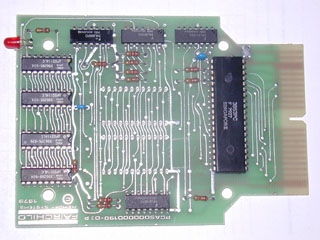
The Saba cart Schach was released in Europe. It has a 3853 chip that creates a normal address bus. It uses a 74LS156 dual 2-line to 4-line decoder to decode addresses in 2K chunks from $00xx to $38xx. $00xx is not used by the cart, since that's where the BIOS is located. $08xx, $10xx and $18xx are used for the game ROM space (two 2332 masked ROMS). $20xx is unused, $28xx is used for 2K of RAM (four 2114 chips), $30xx is unused, and $38xx is hooked up to a flip flop to light up the "I'm thinking" LED.
I use the range $08xx-$20xx as 8K of ROM space for each game. Since the 74LS156 has open-collector outputs, I could just tie those 4 outputs together to get the active low output enable signal for the EPROM, but I also need a signal to use for EPROM address line A12. The $08xx and $10xx lines are already tied together, so I tied $18xx and $20xx together, then I ANDed those 2 combined signals together using 2 diodes and a resistor to make my /OE signal. I used the combined $08xx and $10xx signal for A12.
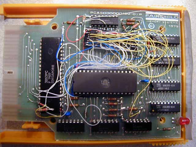
I unsoldered the 2 ROMs and used the left ROM space (with the connector and 3853 at top). The 27C020 has 8 more pins than the 2332 ROM - EPROM pins 5-16 go straight into pins 1-12 on the board. Vpp is "don't care" during normal operation, but to be safe I tied it to +5, since that is right "across the street" on pin 32. I also tied PGM high. EPROM pins 28, 25, 24 and 22 don't go into the board. I put down some electrical tape to make sure nothing shorts (see the pics). Pin 4, A12, goes to the right ROM space's pin 20 (which was a chip select line on the old ROM). Pin 25, A11, goes to the right space's pin 18 (which was A11 on the old ROM). Pin 24, _OE, goes to pin 12 of the 74LS05 (_CPURead, so the EPROM's outputs are selected when the F8 is reading from it). There's a big pad connecting that pin to a resistor, so it's easy to solder to. Pin 22, _CE, is the most complicated. A diode is soldered into a hole that the right ROM left, and another one to a resistor already on the board. One diode goes into the right ROM space's pin 20 (which you already connected above to the new EPROM's pin 4), cathode down. It is marked with the black line. You want to solder the other diode, also cathode down, to the top of the left resistor under the 74LS156 IC. The top of that diode will connect to the top of the other diode, and to a 2.2K resistor, and to the new EPROM's pin 22. The other end of the 2.2K resistor goes to +5. I just made a little vertical triangle with the diode and the left resistor below the 74LS156.
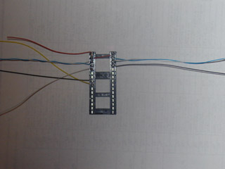
For a manual multigame, the only other thing required is 5 switches or jumpers hooked to A17-A13 to select one of 32 games from a 27C020 EPROM. But I added 3 more chips so that a menu program running on the system can choose the game to play. A 74LS174 hex flip flop is used to latch the data bus to the EPROM. One gate from a 74LS02 quad NOR gate is used to create the CLK signal for the flip flops from the decoded $30xx signal and the _RAMWRITE signal from the 3853. Two more of the NOR gates and three NAND gates from a 74LS00 quad NAND are used with 2 more diodes to detect when the console is reset. This clears the latch, causing the menu program to run.
A diode's cathode is connected to pin 3 of the 3853, and the other diode's cathode to pin 38. The anodes are connected together and tied high with a 2.2K resistor. See the wiring chart below for the other connections.
Since most carts are less than 2K in size, I used the last NOR and NAND gates to OR the EPROM's A12 address line with one more bit from the latch. That way I have 32 4K slots in the first half of the EPROM and 16 8K slots in the second half.
The 3853 in the Schach cart doesn't have the I/O ports that a normal PSU has, so a 2102 can't be connected to play Maze. So I wrote a patch that uses the Schach RAM instead.
Wiring chart for the MultiGame
Pinouts of chips used in the MultiGame
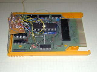
Schach cart with tape in place
Schach cart with EPROM and latch
I bought surface mount ICs so that I could get the circuit to fit inside a normal cart shell. I should have used a carrier board, but instead I used point-to-point soldering (man those pins are close together!)
While Fredric was making a multicart from these instructions, he put together this schematic. Thanks!
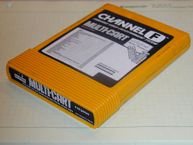
Fredric made me a cool set of labels. Here's a pic: multigame closed up with label.