Mega Duck and Cougar Boy were names of a Game Boy near-clone. The cartridges are a similar size but are not compatible, having a double-sided 0.1"-pitch 36-contact edge connector versus the Game Boy's single-sided 0.05"-pitch 32-contact edge connector.
Ranger_Lannier sent me several cartridges to dump. I was unable to find the cartridge pinout on the web, so I opened the Trap & Turn cart. There's a screw under each corner of the label.
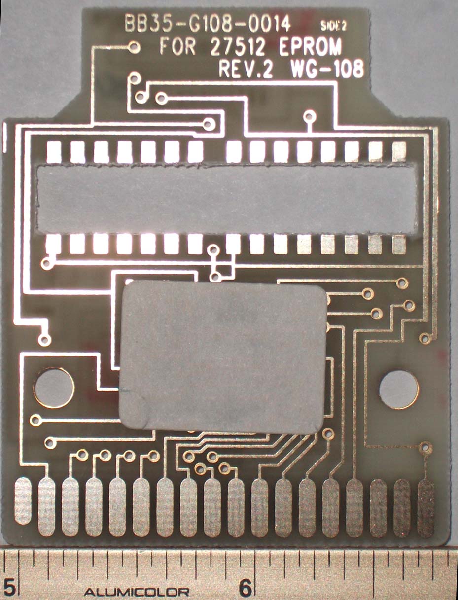
This cart has a single epoxy blob; there are unpopulated pads for a 14-pin DIP IC, a 16-pin DIP IC, and a 16-pin SOIC. Here's the back. The pads for the 2 16-pin ICs are wired in parallel so that one or the other could be used.
6 of the cart contacts are not connected to anything and 2 are connected together, making 29 unique signals. I found a pic of another cart that uses the same signals. The 2nd blob is probably for the bank-select logic.
There is a large rectangular cutout where the two DIPs go so that they can be mounted like a SOIC, with their pins bent out, instead of through-hole. I assume this was done to reduce the required cart thickness.
The IC pads helped ID some of the cartridge contacts: 14-pin DIPs have ground at pin 7 and +5 at pin 14; the leftmost cart contact on the blob side is ground, and the rightmost is +5. On this cart, the +5 contact is shorter than the others, so that it makes contact last.
The connections to the ICs allowed me to ID the chips that would have been used there. The 14-pin DIP had pins 1-3 connected to ground, pins 4 and 5 connected to the cart contacts, and pin 6 connected to the 16-pin ICs. Assuming the 14-pin DIP was combining 2 signals from the cart connector and sending that to the 16-pin IC, and seeing that pins 1-3 were grounded, I determined that the chip was likely a 7408 quad AND or 7432 quad OR.
The 16-pin ICs had pins 4-7 and 10-15 connected to ground, pins 1 and 3 connected to cart contacts, pin 2 to the blob, and pin 9 to pin 6 of the 14-pin DIP. That lead me to think that pin 2 was an output, pins 1 and 3 inputs, and pin 9 a clock or latch signal. The 74174 hex D-type flip flop fits the requirements.
Pin 1 of the 74174 is /clear, so it is likely connected to an active-low reset signal. Pin3 is input to one of the flip flops, and is likely connected to a bit of the data bus.
Next, I connected 5 volts and ground to the cart and used a logic probe to read the other pins. 8 of them were toggling rapidly, which makes sense for a ROM with floating address bus- the toggling pins are the data bus pins. One of them was connected to the 16-pin DIP - likely D0, used to select the bank.
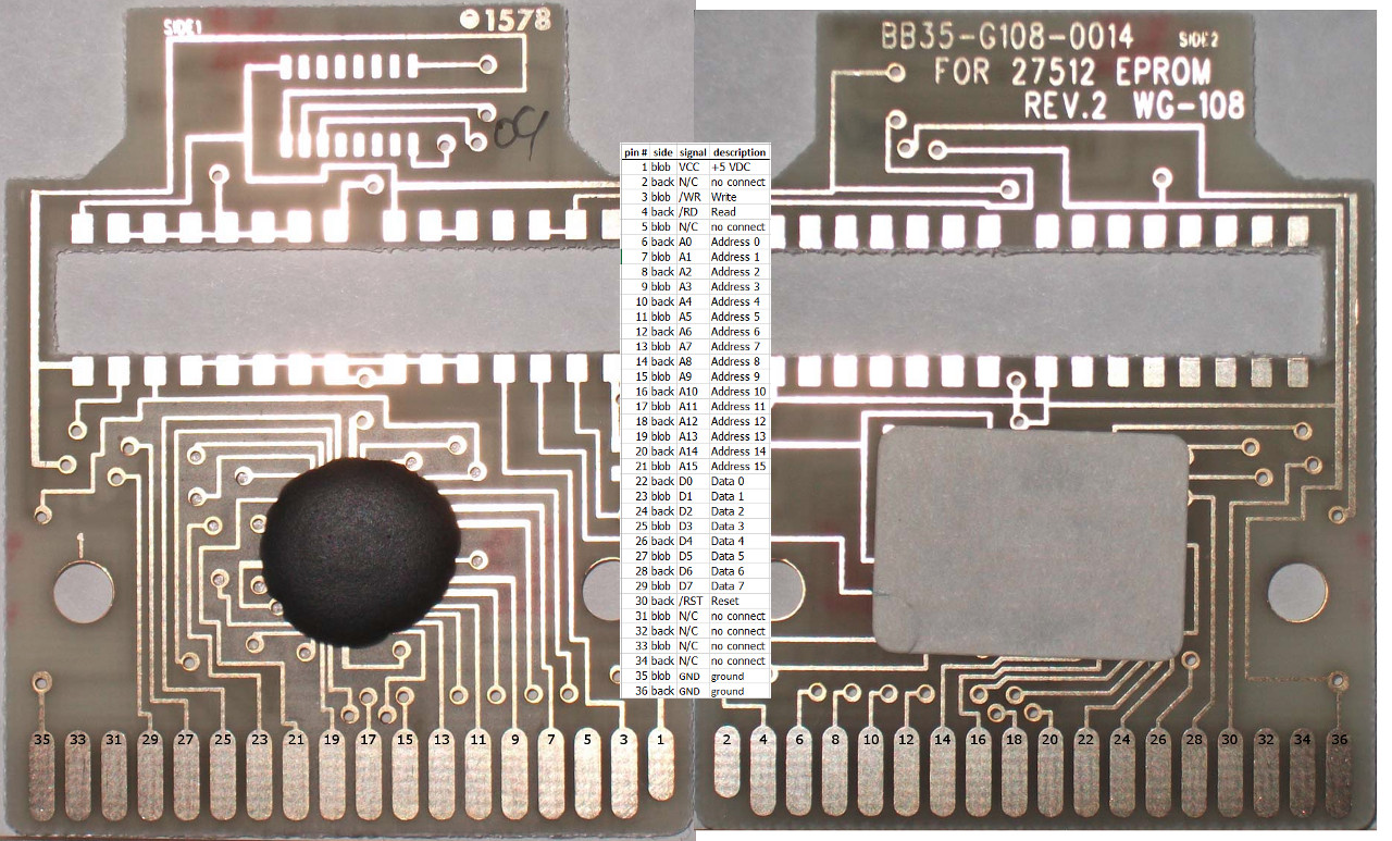
Half of the data bus pins were on one side of the connector and half on the other, which indicates that the contacts are numbered alternating front and back, with all the odd numbers on one side and evens on the other. In addition, to have all the data bus pins numbered sequentially, contact 1 had to be the rightmost pin, either looking at the blob side or the other side.
Taking the rightmost contact on the blob side as #1, the pins I identified mostly match up with the Game Boy cart pinout: 1=+5, 22=D0, 23-29=rest of data bus, 30=reset. Then there are 4 unused pins and 2 grounds. Here's a picture.
Using the Game Boy pinout, the 14-pin DIP has the active-low write signal and A14 routed to it. Since write is active low, that means that the 14-pin DIP is a 7432 quad OR; its output is low on a write with A14=0, otherwise high.
The 16-pin DIP has /reset connected to /clear and D0 connected to the data input. Data output goes to the blob and clock connects to the 14-pin DIP. So if the chips had been populated, a write with A14=0 would latch D0 for the blob to use as the bank #. Reset would clear the bank to 0. This functionality isn't needed for Trap & Turn since it only has 32K.
At this point I felt I had enough info to build a cart dumper, so I found an old .1" pitch 50-pin card edge socket and wired it to a PIC 18F46K22. I wired the data bus to port B and the address bus to ports A and D. I used 3 bits of PORT E for _RD, _WR and _RESET. I used inverted serial mode on the PIC and 2 resistors for communications with a terminal program at 250,000 BPS. I programmed the PIC with the AN1310 bootloader to make programming changes quickly over the serial port.
The code is simple; I used PIC BASIC PRO because it's easy to work with. Output an address, pause a little bit, read the data bus and output that byte to the serial port. I ran it and it looked like it worked - I could see text in the dumped file: "SELECT LEVEL", "LEVEL 1", "LEVEL 2", "LEVEL 3", "LEVEL 4", "PUSH START", "CANT PUT", "SANJO", "ROBIN", "SYLEN", "PICRO".
But then I noticed that every other 1K block was the duplicate of the 1K before it, meaning there was a problem with one of the address bits. Then I dumped the cart twice and compared the 2 dumps, and 62 bytes were different. Almost always, a byte in one file read as 00 instead of the correct value. Every dump had different incorrect bytes in different locations.
At first I thought that maybe I wasn't pausing long enough after setting the address bits, and the data bus hadn't settled before I was reading from it, but I lengthened the delay and the problem persisted.
I was setting the _RD signal low at the beginning of the loop, but after a bit of experimentation, I learned that I needed to set the address bits, pause, set the _RD signal low, pause, read the data bus, then set the _RD signal high. This made every dump the same. But the text I saw before wasn't in the new dump file- instead, I saw "1993 COMMIN", "ENTER YOUR NAME", "BLACK", "WHITE", "GAME OVER", "TIE GAME", "I WON", "YOU WON". Checking the wiring, I noticed the connection to A10 was broken. When I fixed that, I started getting complete, consistent dumps.
The MESS source code lists several carts that have been dumped but the image file is not available. It was handy to have those CRCs to check against these dumps. Four of the dumps had the same CRC as listed in MESS, but 3 did not. The 4 that matched were all 32K in size, and dumped as one bank:
1 32K bank
CB003 Bomb Disposer
CB004 Vex
MD007 Magic Maze
MD009 Trap & Turn
The CRCs for Puppet Knight, Armour Force and 2nd Space did not match. The cart list shows Puppet Knight and Armour Fource as 64K, so I looked at the source code that handles bank switching. There are 2 methods; Puppet Knight has two 32K banks that are swapped by writing 0 or 1 to $B000. Armour Force has four 16K banks- $0000-$3FFF is always bank 0, and $4000-$7FFF is either bank 1, 2 or 3. Writing 0 or 1 to $0001 selects banks 0 and 1, 2 selects banks 0 and 2, and 3 selects banks 0 and 3. 2nd Space is similar, but there are eight 16K banks.
CB008 Puppet Knight 2 banks of 32K - $B000 changed banks

MD014 Armour Force 4 banks of 16K - write 0-3 to address $0001 to change banks
bank 0 and bank 1 0000-3FFF = b0, 4000-7FFF=b1
bank 2 0000-3FFF = b0, 4000-7FFF=b2
bank 3 0000-3FFF = b0, 4000-7FFF=b3

MD028 2nd Space 8 banks of 16K - write 0-7 to address $0001 to change banks
bank 0 and bank 1 0000-3FFF = b0, 4000-7FFF=b1
banks 2-7 0000-3FFF = b0, 4000-7FFF=b2-b7
I haven't figured out bank switching for two Lerncomputer carts- Bilder-Lexikon and Data Bank. Dumping them like 2nd Space, I'm getting 17 (??) unique banks of data for both carts, but the resulting files won't run in MESS. I haven't researched these carts; they might have RAM or other features that are not currently emulated.