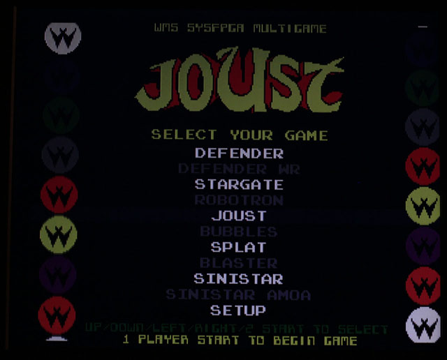
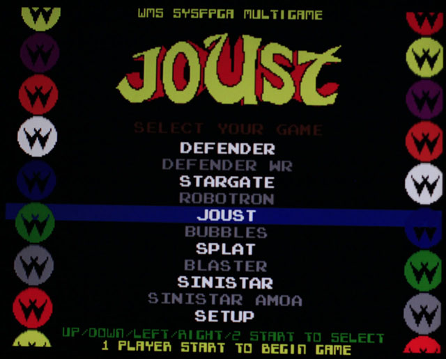
My testing of the JROK WSF board (red PCB, version 2) shows that it is extremely faithful to the original Williams games. One of its added features is VGA output. On some monitors, however, the VGA display is a little dark. It's not very difficult to modify it to be brighter. WARNING-you could easily damage your board by following these directions. I take no responsibility for that. If you aren't comfortable doing this modification, then don't, or at least practice on some expendable electronics first.
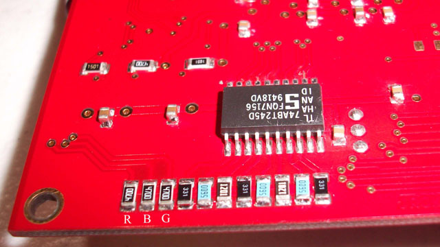
The video output circuitry is similar to that of the original games: 8 bits from the color RAM are broken up into 3 bits of red, 3 bits of green and 2 bits of blue. These 8 TTL signals are converted to 3 analog signals using resistors; the analog signals are then passed through 470 ohm resistors to adjust the brightness. To brighten the image, this resistance needs to be lowered.
This could be done by removing the 3 resistors and replacing them with lower values, but there's an easier way. Piggybacking a resistor connects it in parallel with the original, which always lowers the total resistance; the lower the new resistor's value, the lower the new total resistance. Piggybacking a resistor of the same value results in a total resistance 1/2 of the original. These resistors are 470 ohms (the marking of 4700 is confusing, but means 470x10^0).
I guessed that reducing the resistance to half would be appropriate, so I purchased some 470 ohm surface mount resistors from Digikey. The size used on the boards is known as 1206, based on the length and width in 1/100s of an inch- so a 1206 component is about 1/8" by 1/16". Surface mount parts are typically purchased on long strips of tape that are wound on reels to make automated assembly easier, but a reel of 5000 resistors is a lot to use. Buying the parts singly is easily 25 times more expensive per piece, but much cheaper when only a few (in this case 3) are needed. I did buy a few extra in case of mishap.
On the picture below, I labeled the 3 resistors that need piggybacking as R B and G. There was enough solder already on the existing resistors to allow the new ones to be tacked on top. Using metal tweezers helped make the process easier.
Below are before and after pictures, with the camera set to full manual so it wouldn't adjust to the changed brightness.