TMS-1025 and TMS-1024 are Input/Output Expanders. They multiplex 7 (TMS-1025) or 4 (TMS-1024) 4-bit ports.
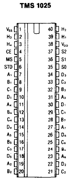
TMS-1025
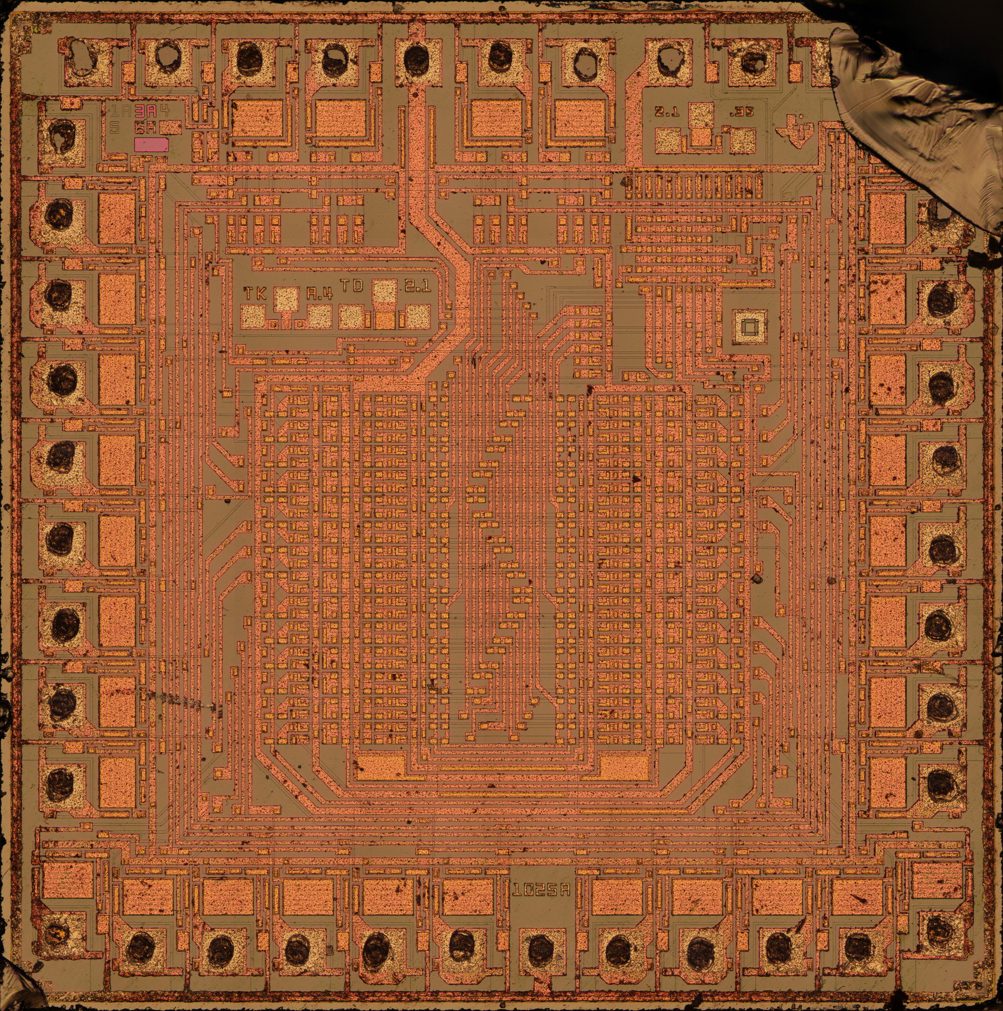
4 MP die shot top metal removed
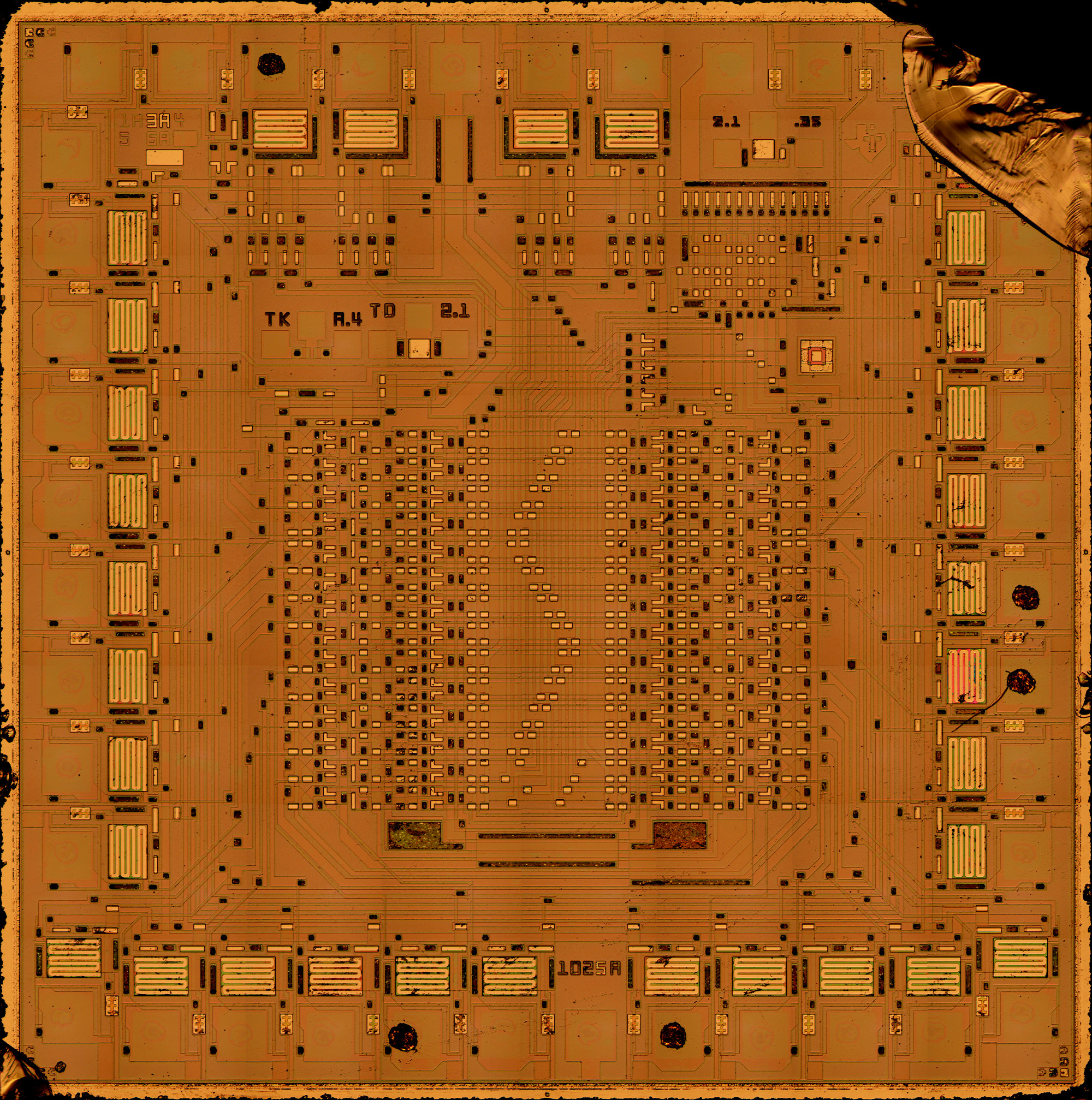
60 MP die shot - 2 layer GIMP XCF - one layer with, one without top metal - 340MB
Pin 1 VSS is at the top, just left of center, with the thick trace coming down. The pads are numbered CCW, so the 3rd pad to the right of VSS is pin 38, VDD. The next 3 pads to the right are the output selection bits. The 2 pins to the left and 2 to the right of pin 1 VSS are the inputs.
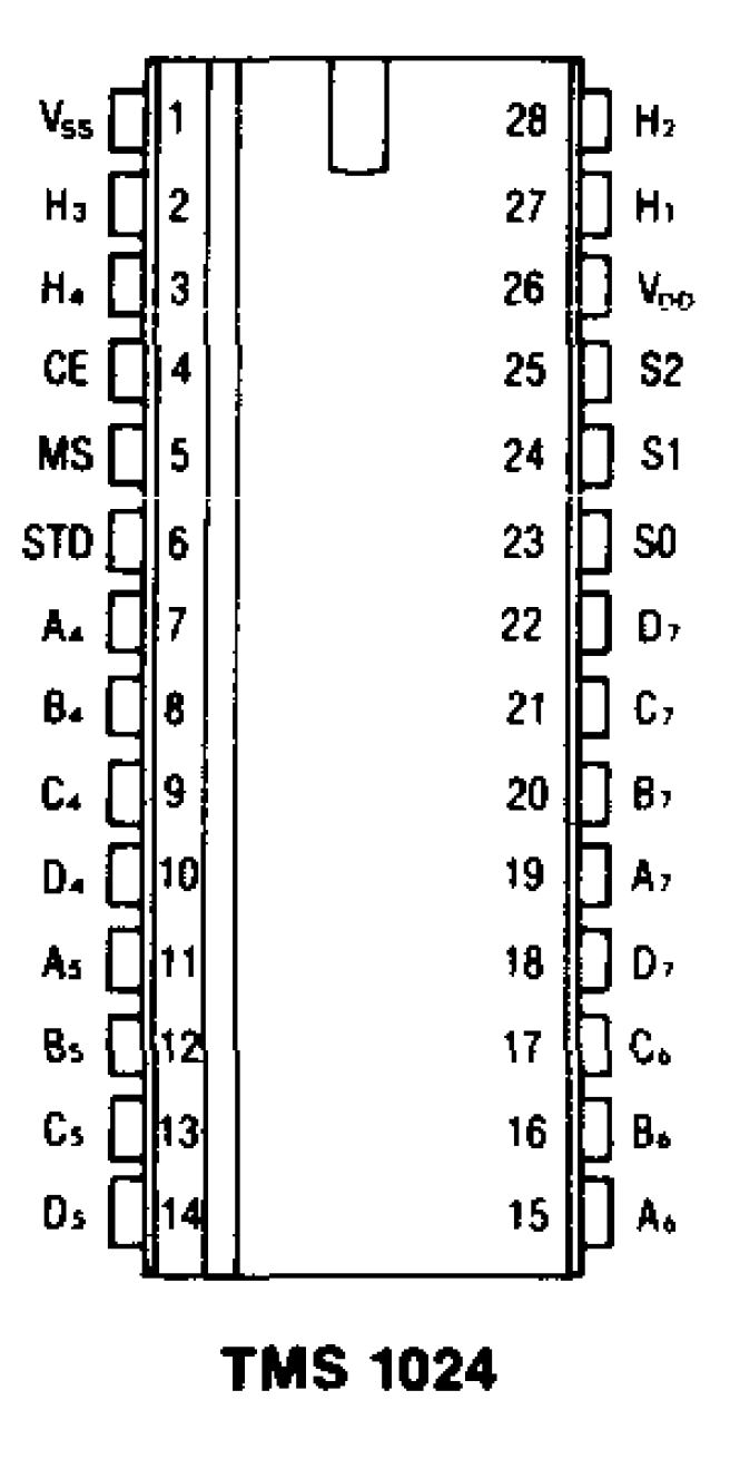
TMS-1024
From this radio service manual pages 9 and 23, I've gleaned a few hints about the TMS1024:
data inputs are H1-H4, output selection bits are S0-S2, latched outputs are A4-D4, A5-D5, A6-D6, A7-D7, STD transfers the data to the latches. CE sounds like Chip Enable; I'm not sure what MS is for, but it's tied high along with CE.
BiggRanger sent me a link to a printer schematic that uses 2 TMS-1025s; one for input, one for output. MS is used to select the I/O direction.
Here are some Saleae Logic captures of a TMS-1024 and a TMS-1025.
I captured some signals from the TMS-1025 while playing Break Up
I controlled a TMS-1024 and a TMS-1025 with a PIC microcontroller and captured signals. For the 1025, I tied A1, B1, C1, D1, A2, B2 low and tied C2, D2, A3, B3, C3, D3 high. For the 1024, I tied A4, B4, C4, D4, A5, B5 low and C5, D5, A7, B7, C7, D7 high.
Data starting on page 6-3 of 1984 Mitsubishi Single Chip Microcontroller Data Book